Tuesday 17 November 2015

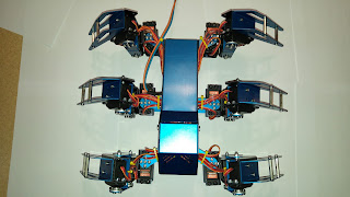
Hexapod Robotic Platform

And as any other obsession begins by seeing either a video or a picture of some insanely well designed project, this one is no exception.

And so it came that for my final project to complete my B-Tech degree I chose to design and build a Hexapod walker.

The concept stage . . . Uhmm. . .


Final CAD Design:


Material:

The chosen material is 1050H14 Aluminium and is probably the most common Aluminium. The majority of the parts are 1.2mm where the body mountings are of 2mm to ensure a good Factor Of Safety (FOS). The canopy and rear cover can be made of any thickness close to 0.8mm as it is not a vital component. Finite Element Analysis were done on all of the parts to ensure that the Hexapod won't fall in on it self.

Anodizing were done in blue and black to give some contrast between the different parts and makes it look interesting.

Servo:


A force of 18Kg.cm can be excerted by each of the 18 6v servos used in the Hexapod. This means when converting the value it can apply a force of 1.67Nm which is quite a lot for a servo. Iding current is specified to be around 100ma per servo and results in a current draw of 1.8A when no force is applied to any of the servos. Maximum current draw (at stall) per servo is specified to be around 4A and means that worst case scenario (would probably never happen due to the geometry of the legs) a current draw of 72A is possible.

Battery:


Which brings us to the next section. To be able to handle high current draw I have chosen a 5000mah 2s 50C Lipo battery to power all of the electronics. An instantaneous current draw of 200A is possible which is definitely an overkill but it should fit nicely inside the bottom of the Hexapod body.

Microprocessor:


Communication via Bluetooth is received and processed accordingly with the aid of the Arduino. Because of its availability and reputation mounting holes for an Arduino Uno R3 were placed on the electronics platform inside the body.

Servo Controller:

Pololu sells a great servo controller going by the name of "Mini Maestro 24-Channel USB Servo Controller" which is ideal for a project where it requires a lot of servo motors to be integrated.

Free to download software with a great looking interface allows you to move each servo individually with a slider bar and finding the correct operating range for your servo model. Running scripts where you move a servo at a frame by frame can also be replayed on power up as well as writing your own code that runs on startup.

HMI (Human Machine Interface):


A standard PlayStation 4 controller were used because of its ergonomics and the fact that everything already works perfectly. It uses a Bluetooth connection which makes it easy to integrate and communicate with the Arduino with the aid of the USB shield and the Bluetooth dongle.

Wireless Communication:


A USB shield for the Arduino fits nicely inside the body and allows a Bluetooth dongle to be connected and communicate with the handheld controller.

So how it works is the PS4 controller takes inputs from the user, the data gets sent via Bluetooth to the Bluetooth dongle on the USB shield and then finally the Arduino reads the values, processes the received values and sends the servo controller specific locations of each leg location.

Ground, Rx & Tx lines goes from the Arduino to the Maestro 24 Servo Controller which allows for serial communication between the two modules.

Programming

As of writing this, the programming has not been finalized yet and I feel that it is the fun part that you have to do yourself.

*But what REALLY helped was this post from HACKADAY which showcases a library for the Arduino to connect to the PlayStation 4 controller through Bluetooth. A big thank you to Kristian Lauszus for writing the library and making it freely available. Go and have a look at what this guy achieved here.

Manufacturing:

All of the CAD files (Solidworks 2015) can be found at Grabcad. https://grabcad.com/library/hexapod-robotic-platform-1

This includes all of the parts (screws included), sub assemblies and final assembly. A simple BOM can be generated to get your parts list.

It is a fully working model which can be built and assembled.

**PLEASE NOTE THAT I TAKE NO RESPONSIBILITY AND IT IS AT YOUR OWN COST TO VERIFY THE CORRECTNESS OF ALL CAD AND MANUFACTURING FILES**

***ONLY condition, if you decide to build this Hexapod, post a picture on the grabcad model page or email me the build because I would love to see other versions***


Thursday 30 April 2015

Delta Parallel Robot

I thought that I should document this before I lose the code, CAD and interest :)

When I came to the end of my Diploma for Mechatronics Engineering, I had to expand/show my knowledge gained.

So I decided on doing a parallel robot. (Little did I know all the trouble that I will have completing this project)

After numerous amount of research and reading theses and forums I found that Trossen Robotics had everything I needed to successfully complete this project.

I had to do the following:

  • Design the parallel platform using CAD
  • Construct control electronics
  • Write software to move the end-effector to desired location by using control electronics

**All the CAD files can be found at Grabcad. (Project name: "Delta Parallel Robot")


The stepper motor controller used was the Toshiba TB6600HG and details can be found here:


**Control kinematics can be found here:


I have changed it a bit so that i could compile it in C:

// Originally from: http://forums.trossenrobotics.com/tutorials/introduction-129/delta-robot-kinematics-3276/

// Delta parallel robot Forward & Inverse Kinematics
// Modified by Frans Roelofse
// September 2013


// robot geometry
 // (look at pics above for explanation)
 const float e = 115.0;     // end effector
 const float f = 457.3;     // base
 const float re = 232.0;
 const float rf = 112.0;

 // trigonometric constants
 const float sqrt3 = sqrt(3.0);
 const float pi = 3.141592653;    // PI
 const float sin120 = sqrt3/2.0;
 const float cos120 = -0.5;      
 const float tan60 = sqrt3;
 const float sin30 = 0.5;
 const float tan30 = 1/sqrt3;

 // forward kinematics: (theta1, theta2, theta3) -> (x0, y0, z0)
 // returned status: 0=OK, -1=non-existing position
 int delta_calcForward(float theta1, float theta2, float theta3, float &x0, float &y0, float &z0) {
     float t = (f-e)*tan30/2;
     float dtr = pi/(float)180.0;

     theta1 *= dtr;
     theta2 *= dtr;
     theta3 *= dtr;

     float y1 = -(t + rf*cos(theta1));
     float z1 = -rf*sin(theta1);

     float y2 = (t + rf*cos(theta2))*sin30;
     float x2 = y2*tan60;
     float z2 = -rf*sin(theta2);

     float y3 = (t + rf*cos(theta3))*sin30;
     float x3 = -y3*tan60;
     float z3 = -rf*sin(theta3);

     float dnm = (y2-y1)*x3-(y3-y1)*x2;

     float w1 = y1*y1 + z1*z1;
     float w2 = x2*x2 + y2*y2 + z2*z2;
     float w3 = x3*x3 + y3*y3 + z3*z3;
   
     // x = (a1*z + b1)/dnm
     float a1 = (z2-z1)*(y3-y1)-(z3-z1)*(y2-y1);
     float b1 = -((w2-w1)*(y3-y1)-(w3-w1)*(y2-y1))/2.0;

     // y = (a2*z + b2)/dnm;
     float a2 = -(z2-z1)*x3+(z3-z1)*x2;
     float b2 = ((w2-w1)*x3 - (w3-w1)*x2)/2.0;

     // a*z^2 + b*z + c = 0
     float a = a1*a1 + a2*a2 + dnm*dnm;
     float b = 2*(a1*b1 + a2*(b2-y1*dnm) - z1*dnm*dnm);
     float c = (b2-y1*dnm)*(b2-y1*dnm) + b1*b1 + dnm*dnm*(z1*z1 - re*re);

     // discriminant
     float d = b*b - (float)4.0*a*c;
     if (d < 0) return -1; // non-existing point

     z0 = -(float)0.5*(b+sqrt(d))/a;
     x0 = (a1*z0 + b1)/dnm;
     y0 = (a2*z0 + b2)/dnm;
     return 0;
 }

 // inverse kinematics
 // helper functions, calculates angle theta1 (for YZ-pane)
 int delta_calcAngleYZ(float x0, float y0, float z0, float &theta) {
     float y1 = -0.5 * 0.57735 * f; // f/2 * tg 30
     y0 -= 0.5 * 0.57735    * e;    // shift center to edge
     // z = a + b*y
     float a = (x0*x0 + y0*y0 + z0*z0 +rf*rf - re*re - y1*y1)/(2*z0);
     float b = (y1-y0)/z0;
     // discriminant
     float d = -(a+b*y1)*(a+b*y1)+rf*(b*b*rf+rf);
     if (d < 0) return -1; // non-existing point
     float yj = (y1 - a*b - sqrt(d))/(b*b + 1); // choosing outer point
     float zj = a + b*yj;
     theta = 180.0*atan(-zj/(y1 - yj))/pi + ((yj>y1)?180.0:0.0);
     return 0;
 }

 // inverse kinematics: (x0, y0, z0) -> (theta1, theta2, theta3)
 // returned status: 0=OK, -1=non-existing position
 int delta_calcInverse(float x0, float y0, float z0, float &theta1, float &theta2, float &theta3) {
     theta1 = theta2 = theta3 = 0;
     int status = delta_calcAngleYZ(x0, y0, z0, theta1);
     if (status == 0) status = delta_calcAngleYZ(x0*cos120 + y0*sin120, y0*cos120-x0*sin120, z0, theta2);  // rotate coords to +120 deg
     if (status == 0) status = delta_calcAngleYZ(x0*cos120 - y0*sin120, y0*cos120+x0*sin120, z0, theta3);  // rotate coords to -120 deg
     return status;
 }